The roadbed is supported on 1x2's which are cantilivered from the stiffeners on the thin walls. Attached simply with screws, the supports are reasonably stiff.

As the roadbed is added to the supports, they become stiffer. Eventually a fascia will be added to the outside of the same supports. The combination of thin wall, stiffener, cantelivered support, roadbed and fascia combine to form a very sturdy assembly. The one exception to this is at the end of the penninsula. Here the roadbed is supported using metal wall brackets.
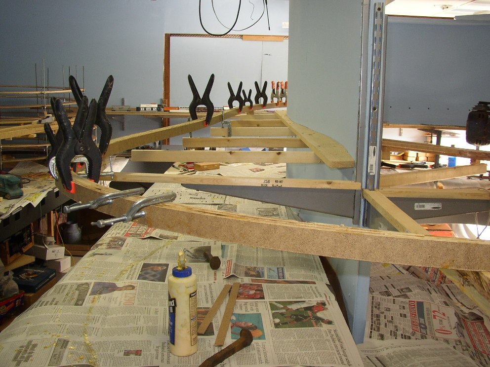
The roadbed is masonite spline ala Lee Nicholas via Joe Fugate. The Masonite comes in 4' x 8' sheets, 1/4 inch thick. The masonite is cut into 1" strips and then reassembled into the roadbed using yellow carpenter's glue. The assemblies are temporarily held together with a series of clamps while the glue cures. I use two full strips in the center of the roadbed. These are glued together and placed in the location of the roadbed. The masonite is flexible and allows for curves and creates natural transitions. On either side of these two I glue two partial strips, leaving a gap every 30" or so to allow the power feeder wires to pass through the roadbed from the power bus to the rails. Outside of these two strips, two more full strips are attached. As the additional strips are add the roadbed gains regidity but stays in the curves set by the first two strips. The completed six strip roadbed is 1 1/2 inches wide or 10.875 scale feet, which easily supports the ties and rails of the track.
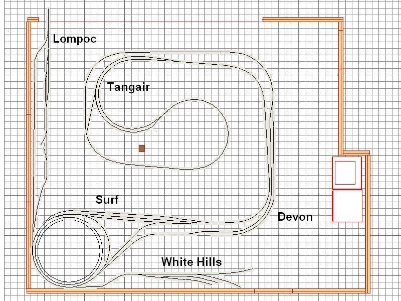
The most difficult portion was the Surf section which was the topic for the last post. After that the roadbed just wound its way along the thin wall to the other end of the layout - about 100 feet away. Beside the passing siding and wye at Surf, the roadbed also included the passing siding at Tangair and the passing siding at Devon. From Surf there is also a grade up to Tangair. The real Southern Pacific climbs the same section as it leaves the Santa Ynez River.
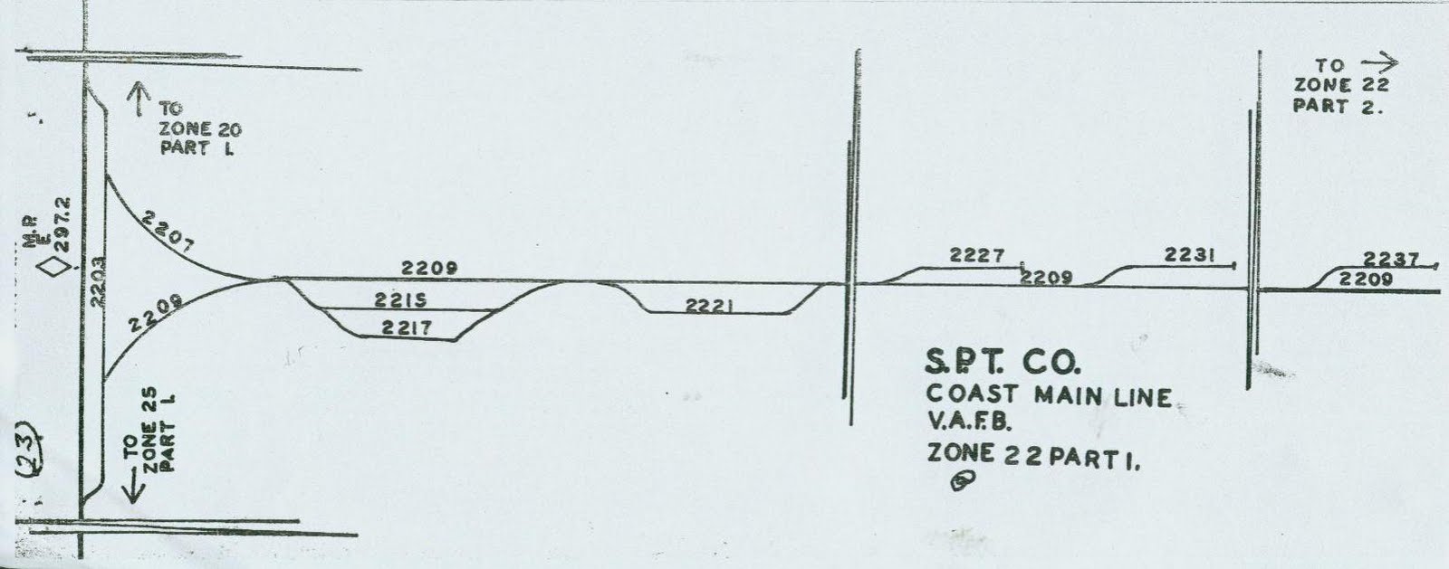
At Tangain on the real Southern Pacific there is another wye - only 5.5 miles from Surf. The tail of the wye extends into Vandenberg Air Force Base. I do not have room for another wye on the layout so Tangair's wye will be only partially modeled. The east leg of the wye will be modeled and will pass through the thin wall to a small shelf which will hold a staging track representing rest of the base. The west leg of the wye will have to be simulated. Fortunately, in real life the wye is hidden in a grove of Eucalyptus trees and is not easily visible from the main line. That gives me the perfect cover on the layout to hide all but the main and siding and the tracks leaving the siding. Here is another SPINS diagram of the Tangair area.
From Tangair on the SP Santa Barbara Subdivision, there is also a grade from Tangair to about half way to Devon. On the real Southern Pacific there is a grade all the way to Devon and a bit beyond as the tracks turn inland from the Pacific Ocean and climb up Shuman Canyon past Casmalia, Devon and a few miles further before dropping down into the Santa Maria Valley toward Guadalupe. Until a few years ago there was a small hill at Devon that actually blocked visibility from one end of the siding to the other. While the same situation exists on the layout the track actually curves the opposite direction. I am hoping to try to at least help the operators feel like they are traveling the same area even if there are some compromises because of the amount of space available in the garage.
Here are some photos of the roadbed under construction and completed as I worked my way from Surf, through Tangain, to Devon and beyond.

Just west of Surf

.
.
.
.
.
.
.
.
.
.
.
.
.
.
East of Tangair

.
.
.
.
.
.
.
.
.
.
.
.
.
.
.
.
.
.
East Tangair switch

.
.
.
.
.
.
.
.
.
.
.
.
.
.
Tangair siding in back. Main track at two masonite strips stage. Eventually there will be a hole punched through the thin wall behind this section allowing the east leg of the Tangair Wye to penetrate and a short staging track will be on the other side.

.
.
.
.
.
.
.
.
.
.
.
.
.
Tangair curve with the east switch of the siding on the right and the west switch on the left. The Tangair wye will be in the center.

.
.
.
.
.
.
.
.
.
.
.
.
.
.
.
.
.
.
West side of the penninsula.

.
.
.
.
.
.
.
.
.
.
.
.
.
.
.
.
.
.
Opposite side of thin wall from Tangair. The tail of the Tangair wye will be on this side of the thin wall just below the roadbed shown here.

.
.
.
.
.
.
.
.
.
.
.
.
.
.
.
.
.
.
Looking east along the Devon siding toward the east Devon switch.

.
.
.
.
.
.
.
.
.
.
.
.
.
.
.
.
.
.
.
West switch at Devon.


No comments:
Post a Comment