Friday, July 3, 2009

More Thin Walls and Another Couple Work Sessions

The concept of the thin walls was not only to minimize the space taken by the wall itself and maximize the use of the space for the railroad, but also to provide for a structure to support two and maybe three decks. While I am not quite done with the first deck, I decided it was better to put up the rest of the walls so I could proceed with at least deck two in the next few months.
.

Our local model railroad club is a round robin type of club so every Tuesday we go to another member's home to run trains, watch videos or work on their layout. I signed up for the Tuesday after Memorial Day 2009 and bought more materials than I needed but wanted to be ready. I got a good turnout but we did not quite get everything accomplished I had desired. It always seems to go a little slower and when you have a bunch of guys all trying to do something it is almost as difficult as herding cats. As luck would have it the following Tuesday was dark as no member had asked to have it so I grabbed it and had the crew back over the next week. We still did not get everything done but the foundation of the walls was in place.
.
We did things a bit different from the first wall seen in the earlier blog post. This time we were supporting the wall on top of the "L-girder" benchwork. Also I wanted the garage door to still operate so the wall had to stop short of the ceiling. There were some questions about structural stability, but that was solved using some curves in the wall as well as putting a top plate along the entire wall. The sections that could had the top plate secured to the ceiling. Those that had to clear the garage door had the top plate on the top of the wall. Again, just like a big "I" beam.
.
We did put up several 2x4 supports floor to ceiling. The 2x4 is screwwed to a block of wood that is secured to the floor using adhesive (liquid nails) and a masonry nail driven with a powder charge. One of these was later removed as it was not connected and the wall was structurally sound without it. In addition, I had 4 steel "C" supports fabricated to support the wall over some of the Santa Barbara area - where the Depot will go.

To form the curvature we took 1x4's or 1x6's and cut the curve into that and used it to make a sandwich with the 1/8" wall in between. In fact we cut four of the "sandwich" boards all at once so that we had a bottom and a top as well as two stiffeners for the two intermediate levels of track. One half of the bottom sandwich was secured to the "L-girder" benchwork and the same was done for the top which was secured to a plate on the ceiling. The wall was then curved into place and the second half of the "sandwich" was added. As the walls progressed around the layout, a lap of 6"-8" was made from one piece of 1/8" ply to the next. Once all the wall was in place under the garage door, another plate was added on top of the sandwich to tie it all together.

We only got two or three sections up during the club work sessions. Afterward I got my wife to help with cutting the walls and screwing on the 1x2's at the lap joints. When it was all up, I used dry wall joint compound to feather the lap joints. After it was smoothed - several applications of dry wall joint compound - I primed and painted them July 3 and we are now good to go.

Here are some photos of the process:


Thursday, July 2, 2009

Structures and a Little Scenery

Until I actually start scratchbuilding structures, I have been putting mock-ups around to help both visitors and myself envision what the scene is to look like. I take photos of the structure and then attach them to cardboard or styrofoam blocks and place them in the approximate location. The photo at the top of the blog is of the Santa Barbara Station. Currently, it is one of the styrofoam block structures. The Carpinteria Depot is from plans that I have copied and pasted on another styrofoam block. I also took a photo of the railroad bridge across Carpinteria Creek and will eventually use a couple of MicroEngineering deck girder bridges to model it.

Here are some of the photos and the mock-ups.


The area around Santa Barbara that I model used to have 3 or 4 lemon packing houses and I plan to model at least two of them. Just for fun I decided to model a lemon grove. I found an on line clinic from the Corona Model Railroad Society http:/www.cmrsclub.org/clinic_trees.html
I also found a lemon stand on-line.  After adding some people, vehicles and smudge pots almost looks like you could stop for some lemonade.

Fascia and Curtains

I have added fascia boards and curtains to the layout to try to hide some of the mess I keep underneath the layout. The fascia is 1/8" masonite. Because I have narrow aisles and wish to enable my operators to pass one another, I have recessed all my carcard boxes. The color of the painted fascia is an approximation of Southern Pacific's grey color they used on later diesels and the dark grey of the 2-tone grey scheme used on the Lark and the Cascade. The curtains are made from garden weed cloth. It comes in 3 foot widths and various lengths - up to 100 feet. I attached it to the back of the fascia using velcro strips.


Track

Just as in other aspects of the railroad, I do not limit my track work to one style. In staging, I have used code 100 with Atlas turnouts. Once out of staging, I have been using Central Valley Tie Strips and Central Valley Turnouts. http://www.cvmw.com/ I use code 83 or code 80 on the mainline, code 70 in the sidings and have a few industrial spurs that are laid with code 55.

Here are some photos of track laying in the West Staging Yard.


.
.
.
.
.
.
.
Here are some photos of the almost completed yard during wiring. I place feeders in every three foot section. In yards these feeders go to strategically placed terminal blocks which are fed off the power bus.


.


.
.
.
.
.
.
.
.
.
.
.
.
.
.
.
.
.
Here are some photos of the Carpinteria area with the Central Valley tie strips being laid in place. The syrofoam block is a place holder for the Carpinteria depot. The section along the thin walls also shows the transition from the homosote to the spline.

Friday, June 26, 2009

Roadbed

I have used two different types of roadbed. The first is easy - homosote. In the yard areas and in staging, I just use homosote as the underlayment for the track. The homosote is attached to 1/2" plywood which is supported from the benchwork using risers to obtain the appropriate height. I did want to have the main line elevated above the yard tracks, sidings and industry spurs. To do this I have used California Roadbed (formerly Homobed http://www.homabed.com/ ) to elevate the main and also to transition from the main to the lower level tracks. Here are some photos of the homosote/plywood sandwich and the elevated track in what will eventually be Carpinteria.


.


.


.
The second style of roadbed is spline. I chose the hardboard (masonite) spline as used by Lee
Nicholas and Joe Fugate (http://siskiyou-railfan.net/e107_plugins/content/content.php?content.15). I have modified it just a bit. I use 6 - 3/4" plys of 1/4" hardboard. I lay in the first two to get the location, curvature and elevation. The spline above the "L-girders" are supported by normal risers. The splines near the thin wall are supported using risers which are cantelivered off the stiffeners of the thin walls. Once the first two hardboard strips are in then I add in 2 additional plys on either side of the center two. One additional piece of hardboard is cut in two on a 45 degree angle and each piece is glued to one side or the other providing a roadbed profile. Ends are staggered to connect one 8 foot section to the next. Some of the splines are arranged to leave holes in the spline about every three feet of so to allow for power feeds for the track. I use yellow carpinter's glue and lots of clamps. The spines are attached to the homosote/plywood by keying one of the center splines into a notch in the homosote/plywood. The height of the spline matches up with the homosote or the elevated homobed. The spline is smoothed using a shure foam plane and a belt sander before the track is layed. Here are some photos:

Traditional Benchwork

So what is traditional benchwork? I guess by that term I mean things like Linn Wescott's "L-Girder" or the old open grid type benchwork. Maybe you can include just flat spaces made from plywood over some support. I used it all. I try not to play favorites. I even used some shelf brackets to support one of the staging yards and hopefully some day some levels above that.

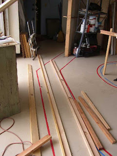
To begin with I needed to transfer my plan to the garage. I had an idea to put tape down on the epoxy floor and then build the benchwork above that so that we could judge where things would go. I purchased some wide colored duct tape and cut the whole roll on the table saw to make narrower rolls. Then I invited my local model railroad club over for a work night. If you do this make sure you have a list of tasks to keep everyone busy. Make them easy tasks so that you do not have to re-explain the job numerous times. Make sure you have some good eats for the crew. It helps to encourage them to come back for later work days.

What I did was have them come over and make "L-girders", lay tape, and put up a few thin wall stiffeners. Here are some photos of the May 29, 2007 work session.


A few days later Gary Siegel came over and we [Gary made the decisions based on the tape on the floor and I assisted. After all he has already built a beautiful layout and has the experience.] assembled the benchwork. It took a couple of days but from there it was easy to lay in the yards and the roadbed. Here are some photos of the finished benchwork.