Tuesday, March 30, 2010

Duck-Unders, Helices, Tight Spaces and Murphy's Law

This entry is a slight diversion from the construction posts of late. After I finally [July 3 to February 12 hiatus] got back on track (pun intended) one of my fans, Bill Decker, and I had an email discussion about the new helix and access problems. We are both agreed that access is important and that no matter how many precautions we take, Murphy will always sneak in and make it not work.

The discussion started when Bill read one of my helix posts and was skeptical about the "counter rotational helix" and the access to the outer helix, especially if the outside of the helix was closed up requiring access through the inner helix. Bill's comments were that Murphy was an optimist!

I would love to have enough room to do a single level layout and not have a helix. I have thought about 3 levels just to get some of what I want in the layout. If I did it on a single level, I would need a space about 25 or 30 feet by 60 or 70 feet. This is the size of a reasonable sized house, and while I already have one of those, the space in the house is put to use for other purposes. That leaves me with the garage. I have negotiated the whole space, with the exception of the washer and dryer. It is a good space but as most model railroaders, planning or building a layout will tell you, there is never enough room. While the helix does take up space, it does efficiently take trains from the first level to the second level.

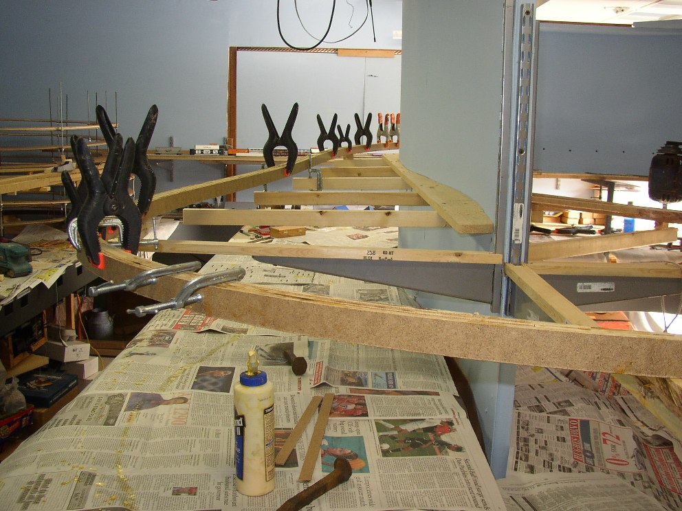
I went round and round on the helix (sorry for the pun) to try to figure out how to do it with out counter rotation. The problem was space and staging locations. I am trying to do a modified Byron Henderson "X-Factor" and access the staging yards requires the current configuration or an extra 4 or 5 feet of garage space. It was also a hard decision to go with the counter rotation because I was concerned about access to the outer helix. As it turns out I have been reaching through the helix to do all sorts of things like install support brackets on the inside wall, grab tools left on the outside that I needed on the inside, etc. Here is a photo from inside of the helix looking through both inner and outer showing the wall supports which were installed by reaching through the helices!


The only place it gets tight are 90 degrees from where the inner and outer helices cross. There the vertical height is quite small. Where they cross I have almost 4 inches and can easily get my hand through. With cars in the helix, I may have to roll/slide them to a wider spot but it is doable. The goal is to not have to do that but as Bill says.....Murphy lives.

To help with the access I am considering some removable scenery on the outside of the helix, but that only covers about 1/3 of the helix the rest is up against the wall. There may be an access in the back corner, but I will have to get a bit thinner.

As we talked more about access, getting old, bad backs, difficulty bending over, we got to talking about duck unders. I do not like duck-unders. I have tried in my design to eliminate them. That is one of the factors that required the counter rotational helix. Both staging yards are in the main room (garage) and are what I would call open. Each has at least 16 inches of vertical clearance.

As it turns out, I have three duck unders. None of the duck-unders are necessary for operations. I have a table saw I store in the garage at one end of the west staging yard. This storage makes it impossible to walk all the way around the layout when the garage door is closed. I use a duck under across from east staging. I put one of the foam 2x2 foam pads under the short duck under and it gets me into the layout.


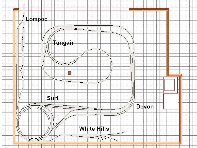
I recently have started using another duck-under as a short cut from the garage entry from the kitchen passing under the tracks just west of double track in Santa Barbara on one side and just east of Summerland on the other side. This saves me a few steps when I want to get into the area near Tangair past the penninsula.


The third duck-under is access to the helix. Back to Murphy. If (when) there are problems in the helix, there is a necessary duck-under to acess the inside. There is another of the foam 2x2 pads there as well. The pad makes it easier to crawl in and stand. the side benefit is it is warmer in my stocking feet as we usually do not wear shoes in the house and I can just step out into the garage and keep my feet warm as I walk around the layout or stand in the helix.


As I said, none of these are required for normal operation. It is about 100 feet from one end of the layout to the other and it can all be done standing - no back worries.

There are still tight spots on the layout to maximize the use of the space. Besides the inner and outer helices, there are tracks going from the wye at Surf to Lompoc and from Lompoc to White Hills. With the tracks and support brackets between the helix and the wall there is not a lot of space.

The one problem that I seem to keep having to deal with is the ladder access to the space over the layout. When I first designed the layout, I tried to put the ladder in a spot I could access it but not have interference from the layout. When I put in the first section of thin wall and the L-girder benchwork for the penninsula, I realized the ladder would not work where I had installed it. As the ladder unfolded, it came into contact with the benchwork and would not be accessable easily without traversing the layout. That ment it would have to be moved. Have you ever tried moving one of the attic access ladders? It is not easy. Fortunately, I called upon my local model railroad club and they came over and we removed it from one hole and put it back in a second hole I had prepared for it. This also meant that all the "stuff" stored above had to be rearranged to accomodate the new hole. At the end of the evening we had the ladder back up and all I needed was to finish the hole and patch the old hole.


After the first level was in, the ladder worked fine. It was a little close, but the lower portion of the ladder is narrower that the upper portion. When we got to the second level the space between the trap door of the access ladder and the thin wall is such there is only enough room for the roadbed and clearance from the thin wall. I will have to have a slightly modified fascia treatment in this area. Fortunately, I could see this problem coming so made a conscious effort to make sure the clearance was there. So far it is working fine. Hopefully, Murphy will not show up here!


Well back to layout construction tomorrow. Hopefully, track laying will begin and I will report early next week on progress. Until then.....

Saturday, March 27, 2010

Second Level Roadbed

After a couple of weeks of snatching time here and there, I have all-but-finished the roadbed for the second level. The only remaining section is the roadbed from Lompoc to White Hills on the branch. That will come in the next week or so while I progress on getting track in on all the roadbed.

The roadbed is supported on 1x2's which are cantilivered from the stiffeners on the thin walls. Attached simply with screws, the supports are reasonably stiff.


As the roadbed is added to the supports, they become stiffer. Eventually a fascia will be added to the outside of the same supports. The combination of thin wall, stiffener, cantelivered support, roadbed and fascia combine to form a very sturdy assembly. The one exception to this is at the end of the penninsula. Here the roadbed is supported using metal wall brackets.


The roadbed is masonite spline ala Lee Nicholas via Joe Fugate. The Masonite comes in 4' x 8' sheets, 1/4 inch thick. The masonite is cut into 1" strips and then reassembled into the roadbed using yellow carpenter's glue. The assemblies are temporarily held together with a series of clamps while the glue cures. I use two full strips in the center of the roadbed. These are glued together and placed in the location of the roadbed. The masonite is flexible and allows for curves and creates natural transitions. On either side of these two I glue two partial strips, leaving a gap every 30" or so to allow the power feeder wires to pass through the roadbed from the power bus to the rails. Outside of these two strips, two more full strips are attached. As the additional strips are add the roadbed gains regidity but stays in the curves set by the first two strips. The completed six strip roadbed is 1 1/2 inches wide or 10.875 scale feet, which easily supports the ties and rails of the track.
The most difficult portion was the Surf section which was the topic for the last post. After that the roadbed just wound its way along the thin wall to the other end of the layout - about 100 feet away. Beside the passing siding and wye at Surf, the roadbed also included the passing siding at Tangair and the passing siding at Devon. From Surf there is also a grade up to Tangair. The real Southern Pacific climbs the same section as it leaves the Santa Ynez River.

At Tangain on the real Southern Pacific there is another wye - only 5.5 miles from Surf. The tail of the wye extends into Vandenberg Air Force Base. I do not have room for another wye on the layout so Tangair's wye will be only partially modeled. The east leg of the wye will be modeled and will pass through the thin wall to a small shelf which will hold a staging track representing rest of the base. The west leg of the wye will have to be simulated. Fortunately, in real life the wye is hidden in a grove of Eucalyptus trees and is not easily visible from the main line. That gives me the perfect cover on the layout to hide all but the main and siding and the tracks leaving the siding. Here is another SPINS diagram of the Tangair area.


From Tangair on the SP Santa Barbara Subdivision, there is also a grade from Tangair to about half way to Devon. On the real Southern Pacific there is a grade all the way to Devon and a bit beyond as the tracks turn inland from the Pacific Ocean and climb up Shuman Canyon past Casmalia, Devon and a few miles further before dropping down into the Santa Maria Valley toward Guadalupe. Until a few years ago there was a small hill at Devon that actually blocked visibility from one end of the siding to the other. While the same situation exists on the layout the track actually curves the opposite direction. I am hoping to try to at least help the operators feel like they are traveling the same area even if there are some compromises because of the amount of space available in the garage.

Here are some photos of the roadbed under construction and completed as I worked my way from Surf, through Tangain, to Devon and beyond.


Just west of Surf

.
.
.
.
.
.
.
.
.
.
.
.
.
.
East of Tangair
.
.
.
.
.
.
.
.
.
.
.
.
.
.
.
.
.
.
East Tangair switch

.
.
.
.
.
.
.
.
.
.
.
.
.
.
Tangair siding in back. Main track at two masonite strips stage. Eventually there will be a hole punched through the thin wall behind this section allowing the east leg of the Tangair Wye to penetrate and a short staging track will be on the other side.


.
.
.
.
.
.
.
.
.
.
.
.
.
Tangair curve with the east switch of the siding on the right and the west switch on the left. The Tangair wye will be in the center.
.
.
.
.
.
.
.
.
.
.
.
.
.
.
.
.
.
.
West side of the penninsula.
.
.
.
.
.
.
.
.
.
.
.
.
.
.
.
.
.
.
Opposite side of thin wall from Tangair. The tail of the Tangair wye will be on this side of the thin wall just below the roadbed shown here.
.
.
.
.
.
.
.
.
.
.
.
.
.
.
.
.
.
.
Looking east along the Devon siding toward the east Devon switch.
.
.
.
.
.
.
.
.
.
.
.
.
.
.
.
.
.
.
.
West switch at Devon.

Saturday, March 20, 2010

Surf

The helix structure being completed - still no track, that will come soon - I began putting in the masonite spline roadbed for the second level. I cut a 4 x 8 masonite sheet into 1" wide strips, 8 feet long. These are reassembled in a six-strip-wide roadbed. The masonite curves easily and I used some templates to make sure the radius was always above 30". The second level consists of mainline, three sidings and junctions for two branches. One, located at Tangair, is on a wye and travels from the main into the HQ area of Vandenberg AFB. I am only modeling the east leg of the wye and a short piece of track that disappears behind the backdrop (thin wall). The second branch is at Surf and is also on a wye and travels to Lompoc and White Hills Junction where another branch climbs San Miguelito Canyon south of Lompoc to the diatomaceous earth mine. I am attempting to model the entire branch but severely compressed.

Surf sits at the mouth of the Santa Ynez river where the main traverses the river on a six-span deck girder bridge.


Beside the wye there was a combination 22 depot before it was torn down November 16, 1971 leaving a small addition which had been added in about 1943. This small building was also torn down and now all that remains is an Amtrak platform which was built in 1994.


.
There were quite a few tracks as can be seen from this SPINS (Southern Pacific Industrial Numbering System) diagram.


.
.
Here are some photos of the area.


Looking north with the wye in the foreground, beyond it the bridge and the Santa Ynez River and in the distance North Vandenberg and Space Launch Complex 2. Lompoc is up the river to the right.


.
....
Looking toward the bridge, with the siding on the left, main in the center and the storage-house track on the right. The west leg of the wye is just beyond the signal.


...
Looking away from the bridge you can see the west leg of the wye taking off on the left and the siding on the right.

The Surf area on the SP Santa Barbara Sub is located just after the 2 1/2 turns of the helix from the first level. I needed to construct some interesting supports for this area since it is wider than most of the other areas. I used some 3/4" square steel tubing to span between the helix and the nearest thin wall. I then utilized the steel tubing to support wood supports for the road bed. I want to maximize the sidings so I changed the order of the tracks from the bridge to allow the siding to come off first. This gives me a siding about 10 1/2 feet long. The storage-house track on the other side of the main is only about 6 feet long. The west leg of the wye is about 32" radius but the east leg is closer to 27" radius. This will probably require restricted speed but then the entire Lompoc Branch is currently under a 10mph speed restriction so that will help make the compressed branch seem a little longer.

I have included here some photos of the supports and spline roadbed, still under construction, in the Surf area on the layout.
.
.


Here is the start of the main line masonite spline with the supports showing between the thin wall and the helix. This areas is approximately 10 feet long and 3 1/2 feet deep from the aisle.
.


.
Here is another view of the same area.
.


.
This view shows the main line spline construction with clamps in place.
..


.
This photo shows an almost completed main line spline with clamps in the area where the bridge will be. On the left is the siding spline.
..


.
This photo looks from the future bridge location toward the helix with the completed main and siding but no house-storage track or wye.
...


Clamps in place on the house-storage track.
..


..
From left to right: siding, main, house-storage tracks.
..


.
Clamps on west leg of wye.
.

.
.
.
.
.
.
.
.
.
.
.
.
.
Clamps on the east leg of the wye. The tail of the wye passes through the thin wall and around the outside of the helix to Lompoc. Looks like I have some repair work to do on the thin wall.
..


This is a photo looking back toward the helix showing the completed main and siding splines.
..
I am still working on the rest of the roadbed and will post more photos soon.

Tuesday, March 16, 2010

New Helix, Part 2

So the last photo of the new helix was posted on March 9, 2010 and showed the laminated helices in place with a few threaded rods in the photo. So this entry will discuss how the helices were assembled and show some photos.

The threaded rods are placed at reasonably regular intervals around the circle. The outer helix has an outer radius of about 33 inches and a perimeter of about 207 inches. I ended up with 9 pairs so the supports are placed about 23 inches apart. The supports are fashioned out of 1/8 inch thick, 3/4 inch wide steel stock. The bar is cut to length and then drilled with a 1/4 inch hole on each end to fit over the 1/4 inch all-thread rod. The threaded rods are placed to fit the holes in the supports and are wide enough to not cause clearance problems. [I used an 85 foot Amtrak Superliner, an 89 foot three tier auto rack and a double stack well car with two standard containers to check clearance - both side and top.] One of the holes is then opened up to form a slot so the support can be put on one threaded rod and then swung under the roadbed and slid onto the other threaded rod.


The steel supports are attached using a hex nut and a fender washer below and another fender washer, a lock washer and another hex nut above.


Here are some photos of the helices going up.


At first I just roughed it in using a block for vertical clearance and a special grade tool. Bob Hamm sent me the grade tool which is quite simple. The tool is made from the same steel bar stock as the roadbed supports. At 12" from one end a hole is drilled and threaded to accept a short threaded section with a lock nut. The threaded section is adjusted to provide for the desired grade and then a short level is placed on top. When the level is level you have your grade.

Here is a photo of the tool itself and in use on the helix along with a photo of the double stack car to show vertical clearance.


I am currently working on extending the masonite spline roadbed from the helix around the second level. I should post about that and the wye at Surf in the next few days. Then I start laying track for the second level. Stay tuned.

Another Work Session

Every once in a while, well actually quite often, I need a kick in the pants to keep working on the layout. So I invite the local club over for a work session. We had another one on February 24, 2010. I had a long list of tasks I wanted to get done. I also wanted to be a little further along than I was when they came over. Even though we did not get through the task list [which seems to mysteriously grow as we progress!] we did get a few things accomplished.

One of the younger members, Michael Lopes, brought two of his locomotives over thinking I had gotten a lot further since he helped me around New Years. Michael is so optimistic. Instead I handed him the camera while I tried to supervise and work on the helix. [I will cover part 2 and 3 of the helix construction in the next two or three posts.]

Some of the crew worked on putting up some shelf brackets at the end of the penninsula which will hold the big turnback loop of the second level. I had originally hoped to put 5 brackets up so the span would not be so great but putting 5 standards on three sides of a 2X4 appeared to difficult so they monted 3 standards instead.


Then they joined the other group who was measuring, cutting and installing roadbed supports. These supports are attached to the stiffeners on the thin walls.

John Ryan measuring and marking roadbed supports.


Art Sylvester, Joe Heumphreus and Art Bosse planning their work.


Art Sylvester working on his drilling technique.


Art Aldritt showing his happy sawing technique.


Jim Felland getting ready to saw.


Completed and installed roadbed supports.


That is all for now. Come back for the next installments of the helix adventure.