Tuesday, March 9, 2010

New Helix, Part 1

I had a helix installed, but it was only temporary to connect the end of track on the first level back to the staging yard. [There is about a 5 inch difference from the east end of level one and the west end.] What I need for the finished layout, is actually two helices. I need one that connects the west end of level one to the east end of level two, and another to connect the top currently at the west end of level two back to the west staging yard

As I mentioned in my post of February 12, 2010, while I was at the Hartford Convention, I attended a clinic by Bob Hamm on Helix construction. Bob uses threaded rod and laminated plywood roadbed to support his helices. I had done that in my earlier temporary helix. The big difference in construction was the subroadbed on my temporary helix was a polygon formed by straight sections with an angle cut allowing for a complete circle when laminated together. Bob does some calculations and then uses what he calls "banana cuts". The outer radius of the roadbed is also used for the inner radius, moving the center of the circle so the inside off-set outer radius curve lines up with the expected inner radius at the ends of 90 degree sections. This results in a roadbed segment that is wider in the center than on the ends and does, sort-of, have a banana shape. I cut the sections from 1/8" luan plywood, "ganging" about 4 or 5 together to cut them. I laminating them together with about a 30% off-set so the joints are not over previous joints. I had scribed the curves in the seal on my driveway and just assembled the helix subroadbed on the ground. As I continued around, I placed waxed paper between the levels to keep them separated. The inside "top-to-bottom" helix is about 6 1/2 turns. This became somewhat complicated but I just kept laying more wax paper and kept laminating until I had enough turns.


The real complication is that the outer helix that goes from level one to level two, while only 2 1/2 turns, actually turns the opposite direction. That is the inside one rises in a counter-clockwise direction when viewed from the top. The outside helix rises in a clockwise direction. I have jokingly called this counter rotational. the complication comes when you put in the threaded rods and sub-roadbed supports. The helices cross each other's plane twice per rotation so reaching through from the inside to the outside is complex. This may be necessary if, or maybe I should say when, there are derailments in the helix. Eventually, access will be limited to the inside only, once scenery hides the helices.

Here are a few photos of marking and cutting the banana curves.


Here are photos of laminating the helices on the driveway.


And here are the completed laminated helices in position with a few of the threaded rods in place but before the helices were erected.


I will post some more soon on the actual assembly of the helices to make them usable.

Sunday, February 14, 2010

Work Session 10-6-2009

I invited my friends and fellow members in the South Coast Society of Model Engineers over to help me with a few jobs on the layout. We meet most Tuesdays at members homes and once a month for a business meeting where we also share new acquisitions, stories of railfanning adventures, and other railroad related events. The meetings at members homes can be running on a members layouts, work sessions on members layouts, or just watching videos with friends.

I had finished the walls but wanted to put some additional stiffeners which would also later serve as supports for the second level. The stiffeners or external ribs were described briefly in the Thin Walls post of June 23, 2009. Most of the stiffeners were cut previously when we were putting up the new thin walls (see the July 3, 2009 post). Because the walls have some curvature to them the stiffeners are cut to match the curvature. Because the curvature should be the same at the top as the bottom, when the walls were erected three or four identical stiffeners were cut. It was quite easy then to attach the stiffeners to the new walls. Since the walls are only 1/8" thick the stiffeners are secured using 1 1/4" dry wall screws from the opposite side of the wall.


John Ryan and Michael Lopez holding a stiffener over Summerland


John Ryan and Bob Lyon holding a stiffener over Carpinteria


John Ryan securing a stiffener over La Patera from the Carpinteria side


Joe Heumphreus securing the stiffener over Summerland from the back side.


The problem came when stiffeners had to be cut for the old thin walls that were errected initially. Each individual stiffener had to be measured and cut.


Walter Naumann measuring a stiffener for the old thin wall


In addition to the stiffeners, I had a bookcase that I wanted to put some doors on so that I could hand a blackboard for crew announcements and a crew call board. Two of the club members tackled that task. By the end of the evening we had accomplished much and another step was accomplished.


Art Sylvester and Jim Felland work on the bookcase doors


The blackboard and crew call board on the finished doors

Friday, February 12, 2010

Where Has All the Time Gone?

It has been over seven months since I posted anything on my blog. Where has the time gone? I guess I need to get going again on the Santa Barbara Subdivision. I did not realize that people actually read and followed the exploits in the garage until Bill Decker approached me in October at the Southern Pacific Historical and Technical Society Convention in San Luis Obispo asking why I had not posted since July 3, 2009. I told him I would be posting soon. When Bill saw me at the end of January this year, he asked again. So, Bill, this post is for you!


The day after the last post I flew to Hartford, Connecticut to participate in the 2009 NMRA convention. The week was wonderful and sometime in the near future I will tell you all a little about the week. The following three weeks, my wife and I traveled north to Prince Edward Island, Nova Scotia, New Brunswick, Maine and returned south to Massachusetts (Martha's Vineyard) and Connecticut before returning home.


In October my wife traveled with me to Colorado to attend Rocky Ops North where we joined with other model railroad operators from around the country, operating on some great layouts.


I had a work day on the railroad October 6, 2009 with help from my local model railroad club. I will report on that in a separate post. We put in some supports for a second level. Yes, I am going up to level two.


At the Hartford convention I attended a clinic by Bob Hamm about building a helix. Even though I had a helix in already it was temporary and I am now in the process of putting in another larger more complex helix. More on another post.


Right now I am trying to get over a psychological "hump". Many of the areas of the layout have accumulated material on the horizontal surfaces. A problem that I am constantly battling.


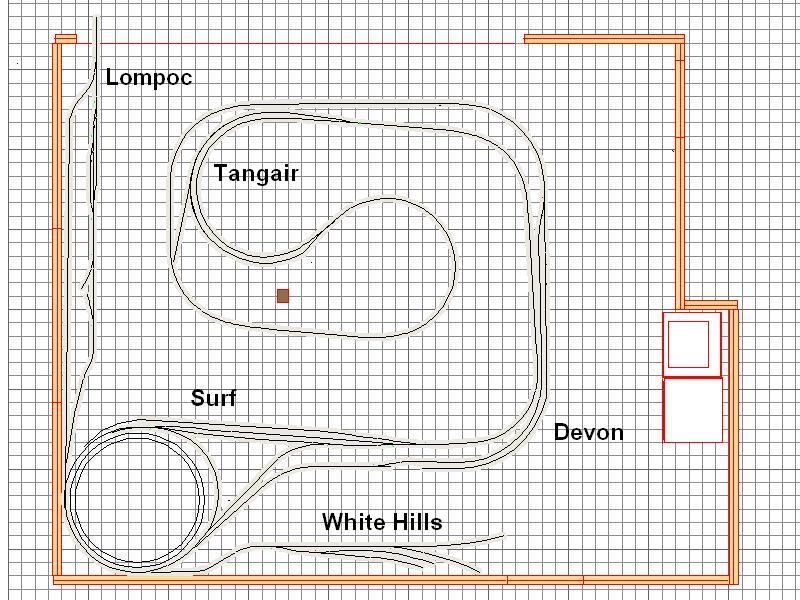
The second level will include Surf and the branch to Lompoc and the White Hills diatomaceous mine complex. The main line will continue north past Vandenberg Air Force Base and approach the Santa Maria Valley. I will try to be better at making progress and reporting to all of you on that progress.


Tie strips and hoppers on the shelf where the diatomaceous mine is planned.

Friday, July 3, 2009

More Thin Walls and Another Couple Work Sessions

The concept of the thin walls was not only to minimize the space taken by the wall itself and maximize the use of the space for the railroad, but also to provide for a structure to support two and maybe three decks. While I am not quite done with the first deck, I decided it was better to put up the rest of the walls so I could proceed with at least deck two in the next few months.
.

Our local model railroad club is a round robin type of club so every Tuesday we go to another member's home to run trains, watch videos or work on their layout. I signed up for the Tuesday after Memorial Day 2009 and bought more materials than I needed but wanted to be ready. I got a good turnout but we did not quite get everything accomplished I had desired. It always seems to go a little slower and when you have a bunch of guys all trying to do something it is almost as difficult as herding cats. As luck would have it the following Tuesday was dark as no member had asked to have it so I grabbed it and had the crew back over the next week. We still did not get everything done but the foundation of the walls was in place.
.
We did things a bit different from the first wall seen in the earlier blog post. This time we were supporting the wall on top of the "L-girder" benchwork. Also I wanted the garage door to still operate so the wall had to stop short of the ceiling. There were some questions about structural stability, but that was solved using some curves in the wall as well as putting a top plate along the entire wall. The sections that could had the top plate secured to the ceiling. Those that had to clear the garage door had the top plate on the top of the wall. Again, just like a big "I" beam.
.
We did put up several 2x4 supports floor to ceiling. The 2x4 is screwwed to a block of wood that is secured to the floor using adhesive (liquid nails) and a masonry nail driven with a powder charge. One of these was later removed as it was not connected and the wall was structurally sound without it. In addition, I had 4 steel "C" supports fabricated to support the wall over some of the Santa Barbara area - where the Depot will go.

To form the curvature we took 1x4's or 1x6's and cut the curve into that and used it to make a sandwich with the 1/8" wall in between. In fact we cut four of the "sandwich" boards all at once so that we had a bottom and a top as well as two stiffeners for the two intermediate levels of track. One half of the bottom sandwich was secured to the "L-girder" benchwork and the same was done for the top which was secured to a plate on the ceiling. The wall was then curved into place and the second half of the "sandwich" was added. As the walls progressed around the layout, a lap of 6"-8" was made from one piece of 1/8" ply to the next. Once all the wall was in place under the garage door, another plate was added on top of the sandwich to tie it all together.

We only got two or three sections up during the club work sessions. Afterward I got my wife to help with cutting the walls and screwing on the 1x2's at the lap joints. When it was all up, I used dry wall joint compound to feather the lap joints. After it was smoothed - several applications of dry wall joint compound - I primed and painted them July 3 and we are now good to go.

Here are some photos of the process:


Thursday, July 2, 2009

Structures and a Little Scenery

Until I actually start scratchbuilding structures, I have been putting mock-ups around to help both visitors and myself envision what the scene is to look like. I take photos of the structure and then attach them to cardboard or styrofoam blocks and place them in the approximate location. The photo at the top of the blog is of the Santa Barbara Station. Currently, it is one of the styrofoam block structures. The Carpinteria Depot is from plans that I have copied and pasted on another styrofoam block. I also took a photo of the railroad bridge across Carpinteria Creek and will eventually use a couple of MicroEngineering deck girder bridges to model it.

Here are some of the photos and the mock-ups.


The area around Santa Barbara that I model used to have 3 or 4 lemon packing houses and I plan to model at least two of them. Just for fun I decided to model a lemon grove. I found an on line clinic from the Corona Model Railroad Society http:/www.cmrsclub.org/clinic_trees.html
I also found a lemon stand on-line.  After adding some people, vehicles and smudge pots almost looks like you could stop for some lemonade.

Fascia and Curtains

I have added fascia boards and curtains to the layout to try to hide some of the mess I keep underneath the layout. The fascia is 1/8" masonite. Because I have narrow aisles and wish to enable my operators to pass one another, I have recessed all my carcard boxes. The color of the painted fascia is an approximation of Southern Pacific's grey color they used on later diesels and the dark grey of the 2-tone grey scheme used on the Lark and the Cascade. The curtains are made from garden weed cloth. It comes in 3 foot widths and various lengths - up to 100 feet. I attached it to the back of the fascia using velcro strips.


Track

Just as in other aspects of the railroad, I do not limit my track work to one style. In staging, I have used code 100 with Atlas turnouts. Once out of staging, I have been using Central Valley Tie Strips and Central Valley Turnouts. http://www.cvmw.com/ I use code 83 or code 80 on the mainline, code 70 in the sidings and have a few industrial spurs that are laid with code 55.

Here are some photos of track laying in the West Staging Yard.


.
.
.
.
.
.
.
Here are some photos of the almost completed yard during wiring. I place feeders in every three foot section. In yards these feeders go to strategically placed terminal blocks which are fed off the power bus.


.


.
.
.
.
.
.
.
.
.
.
.
.
.
.
.
.
.
Here are some photos of the Carpinteria area with the Central Valley tie strips being laid in place. The syrofoam block is a place holder for the Carpinteria depot. The section along the thin walls also shows the transition from the homosote to the spline.